
Hexatorq Hinges
Advanex KATO Hexatorq Hinges
Conventional spring hinges, when used in high-temperature environments or applications where high usage cycles lead to increased hinge temperature, may lose their stiffness and become stuck, causing damage to mating parts.
KATO Hexatorq Hinges (KH) feature an innovative design utilizing modern plastic resin that does not require lubrication. In high-temperature applications, Hexatorq hinges exhibit a predictable torque decrease, returning to the original torque values after a brief cooling period. This ensures that no damage occurs to the parts due to locking.
Hexatorq hinges are available in standard sizes to meet the requirements of common applications. Design, durability, and product validation tests have been conducted. By using KATO Hexatorq hinges, it is possible to significantly reduce design and production lead times.
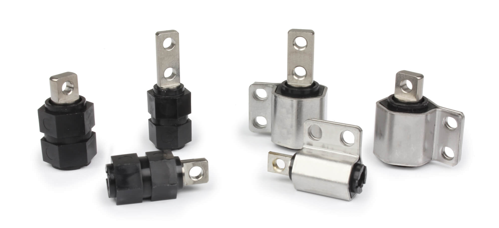
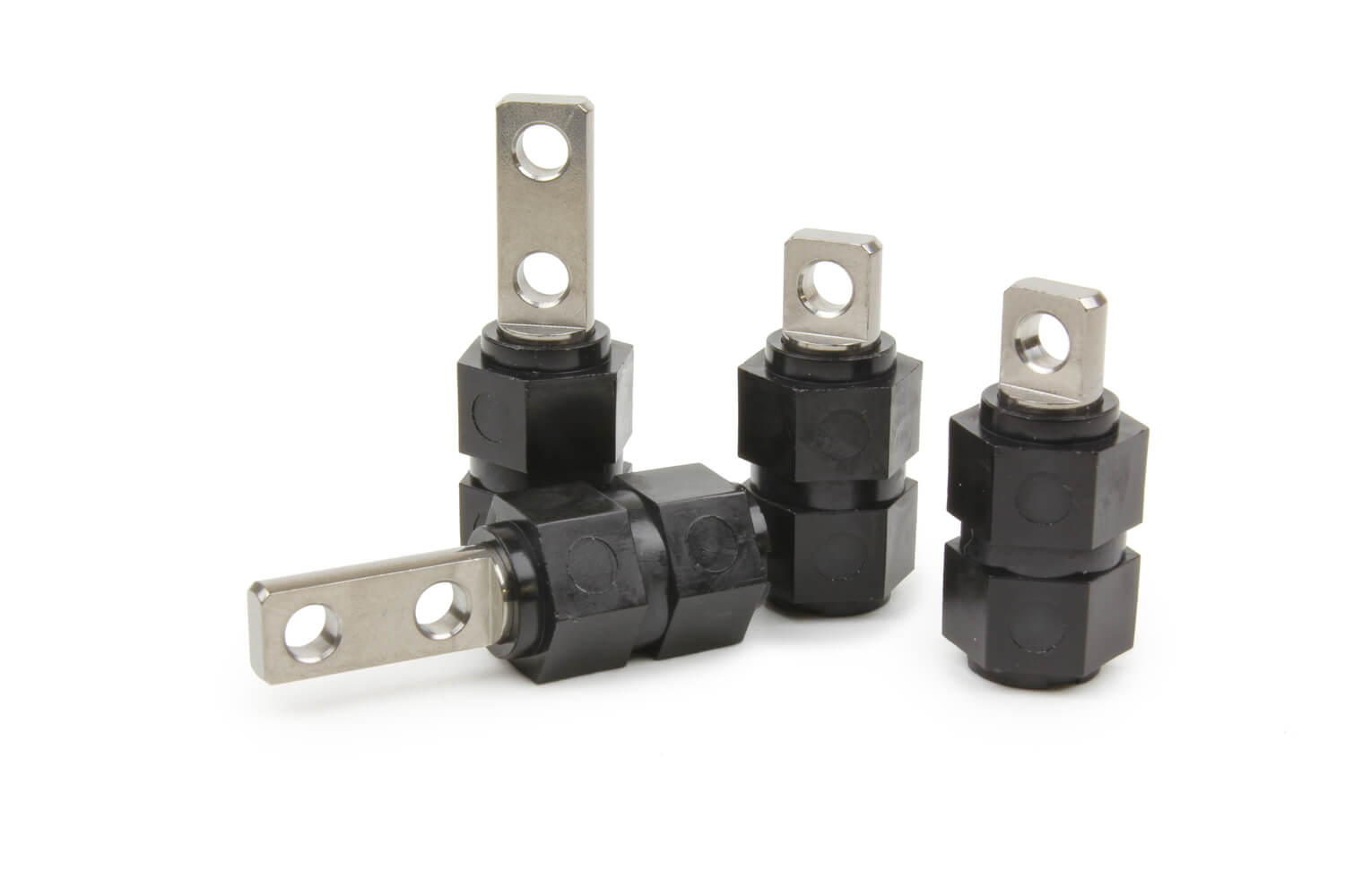
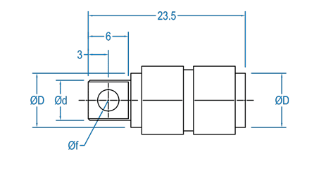
A – Without support
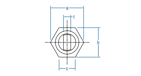
(Assembly in HEX housing)
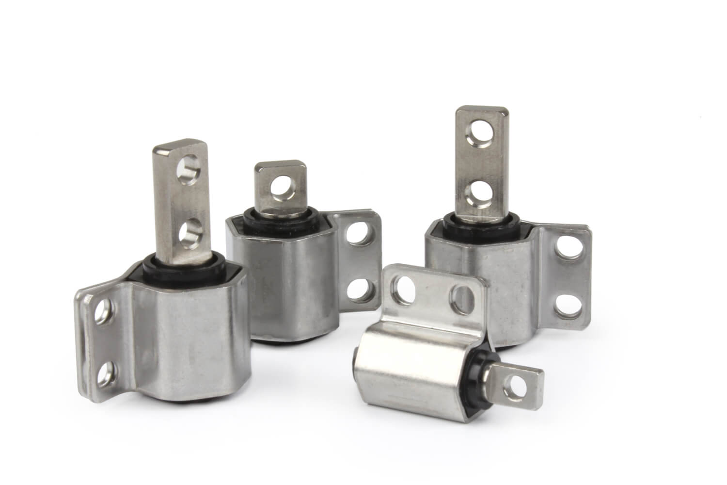
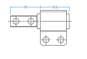
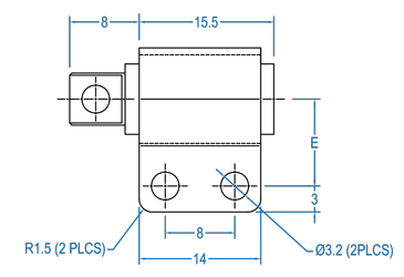
B – With support
(Left or right assembly)
Features and Benefits
• Constant torque, designed for 30,000 cycles and beyond without failures.
• Smooth operation with a 360° working range.
• Maintains position throughout the working range without elastic rebound.
• Corrosion-resistant stainless steel with a special resin design.
• Lightweight, compact, maximizing space and weight savings.
• Hexagonal configuration allows easy mounting in mold housing without
brackets.
• No lubrication required! Eliminates the possibility of contamination and
corrosion of sensitive parts.
• FOD-free design (Foreign Object Debris Free), absence of metal-on-metal
friction means no damage caused by the presence of metallic particles.
Article Code
A standard range is available, but custom shaft configurations are available. Contact technical support for more information. Example of a standard Hexatorq part code:
KH 5 2 B 050 R
1 2 3 4 5 6
| 1 Type |
2 Ø Shaft (mm) |
3 N. of shaft holes |
4 Support |
5 Torque value (kgf-mm) |
6 Assembly |
|---|---|---|---|---|---|
| KH KATO Hinge |
5.0 6.0 7.0 |
1 2 |
A - Without support B - With support |
25 50 75 100 125 150 |
(Only for B models with support) L - Left R - Right |
| Without support | With support | Without support | With support | ||
|---|---|---|---|---|---|
| Right | Left | Right | Left | ||
| KH51A025 | KH51B025R | KH51B025L | KH52A025 | KH52B025R | KH52B025L |
| KH51A050 | KH51B050R | KH51B050L | KH52A050 | KH52B050R | KH52B050L |
| KH61A075 | KH61B075R | KH61B075L | KH62A075 | KH62B075R | KH62B075L |
| KH61A100 | KH61B100R | KH61B100L | KH62A100 | KH62B100R | KH62B100L |
| KH71A125 | KH71B125R | KH71B125L | KH72A125 | KH72B125R | KH72B125L |
| KH71A150 | KH71B150R | KH71B150L | KH72A150 | KH72B150R | KH72B150L |
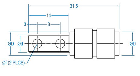
Specifications - All dimensions for metric models are in mm
Without support
With support
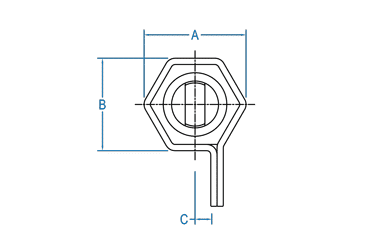
| Code |
Torque |
With support | Without support |
D |
Diameters d |
f |
t |
||||||
|---|---|---|---|---|---|---|---|---|---|---|---|---|---|
| kgf-mm | lbf-in | A | B | C | E | a | b | c | |||||
| KH51[*]025 KH52[*]025 |
25.0 | 2.2 | 11.2 | 9.8 | 1.5 | 9.0 | 9.3 | 8.2 | 4.8 | 7.0 | 5.0 | 2.7 | 2.0 |
| KH51[*]050 KH52[*]050 |
50.0 | 4.3 | 11.2 | 9.8 | 1.5 | 9.0 | 9.3 | 8.2 | 4.8 | 7.0 | 5.0 | 2.7 | 2.0 |
| KH61[*]075 KH62[*]075 |
75.0 | 6.5 | 13.4 | 11.8 | 2.0 | 10.0 | 11.6 | 10.2 | 5.8 | 8.1 | 6.0 | 3.2 | 2.5 |
| KH61[*]100 KH62[*]100 |
100.0 | 8.7 | 13.4 | 11.8 | 2.0 | 10.0 | 11.6 | 10.2 | 5.8 | 8.1 | 6.0 | 3.2 | 2.5 |
| KH71[*]125 KH72[*]125 |
125.0 | 10.9 | 16.1 | 14.2 | 2.5 | 11.0 | 14.0 | 12.2 | 7.0 | 10.2 | 7.0 | 3.2 | 3.0 |
| KH71[*]150 KH72[*]150 |
150.0 | 13.0 | 16.1 | 14.2 | 2.5 | 11.0 | 14.0 | 12.2 | 7.0 | 10.2 | 7.0 | 3.2 | 3.0 |
Calculating the torque requirements
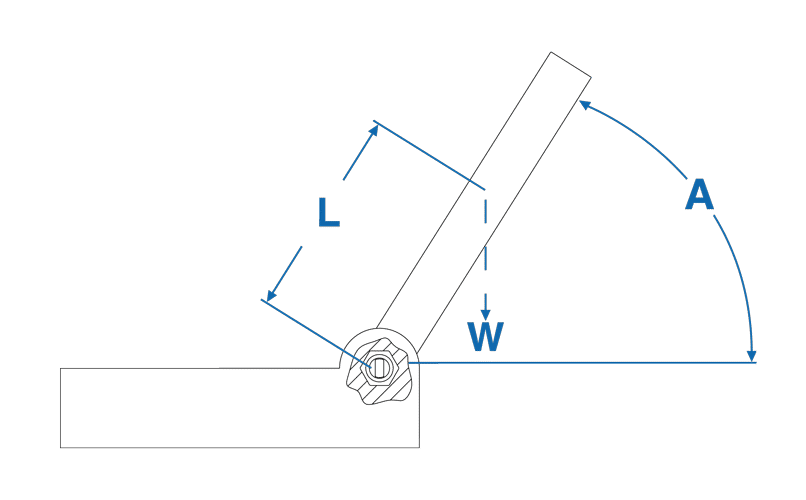
Use the following formula: T = W x L x Cos(A)
Where:
A – Angle
L – Distance from the Center of Gravity
T – Torque
W – Weight of the object to be supported
Example:
W = 2 lbs – L= 4″ inch – Angle = 0°
T = (2) (4) Cos(0°)
T = 8lbf – in.
Example:
W = 0.9Kg L= 101.6mm Angle = 0°
T = (2) (4) Cos(0°)
T = 92.16 kgf-mm
Notes:
1. To convert from lbf-in to kgf-mm, multiply by 11.5212
2. To convert from kgf-mm to lbf-in, multiply by 0.0868
3. If 2 hinges are used: 8 lb-in/2 = 4 lb-in per hinge – 92.16 kgf-mm/2 = 46,08 kgf-mm per hinge