
INSTALLATION
Metric and unified pitches, with and without tang driver
Threaded inserts are designed to be installed in holes with suitable tapping and take the tolerance of the housing thread. For example, tapping for threaded inserts M6 (sometimes defined as EG-M6 or STI M6) with a tap in tolerance EG-M6 6H or STI-M6 6H, will produce an M6 6H thread once the insert is installed.
A correct execution of the mechanical processing of the insert housing determines the final tolerance class and facilitates the installation of threaded inserts. An incorrect execution of the housing tapping, in addition to being a potential cause of non-compliance, is often the cause of installation problems for threaded inserts.
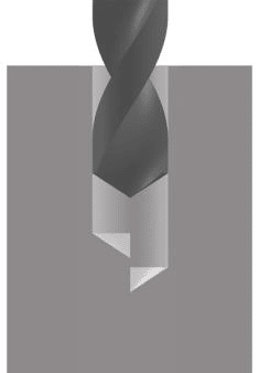
Step 1 – Drilling
The drill diameter and drilling depth must be chosen based on the data provided by the drilling tables below. The tapping diameters must comply with the NASM33537 and MA1567 standards and must be measured after tapping operations and any subsequent treatments (anodizing, chemical film, etc.).
The recommended pilot hole is to be taken as a suggestion based on the characteristics of the material to be drilled and to allow for a long life of the tap on tough materials. These are average values that are adequate for most applications, but there may be specific applications that require variations to achieve the correct tapping diameters and tolerances. For example, adjustments should be made in case of coatings or treatments (anodizing, chemical film, etc.).
The drilling depth for blind holes depends on the thread installation method. Consideration should be given to any countersink of the hole, the type of tap used, and whether the tang, if used, is removed (Tangless® threads have no tang). Threaded inserts are typically installed from ¾ to 1-½ times the pitch below the surface of the countersunk hole. They can also be installed at different depths in cases of specific space limitations. Without countersinking, inserts can be installed from ¼ to ½ times the pitch below the surface.
The minimum material thickness, in case no countersink is made, is the nominal thickness of the thread to be installed
(1 – 1.5 – 2 – 2.5 – 3 d)


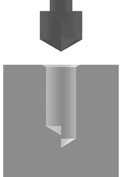
Step 2 – Countersink
Before tapping, it is advisable to countersink the hole at 120° + 5° with a diameter equal to M, as indicated in the tables. This helps avoid thin material ridges at the hole entrance, which can be easily damaged. The 120° countersink is used because 60° on each side is the same angle as the thread and the insert's wire section. This combination makes the insert installation operation faster and safer. The values F and H are calculated with a countersink depth of 1/2 the pitch.
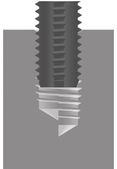
Step 3 – Tapping
For the depth of tapping in blind holes, the type of tap used must be considered. Refer to the tables for indicative data to guide you. The tapping depth parameter in the table is calculated considering a normal installation with countersinking. If countersinking is not performed, the depth can be reduced.
The H or B tolerance class of the finished thread with the installed insert depends on the tap tolerance. The installed insert will have a tolerance within the parameters of the tap tolerance. Typically, the tighter 4H or 3B class is used in military or aerospace applications and is recommended for use with locking threads to achieve better braking parameters and where greater security is required. The 5H or 6H or 2B class is suitable for most industrial and commercial applications and for repairing damaged threads.
Step 4 – Inspection
The thread tolerance class must be achieved before installing the insert. Any treatments or surface coatings can significantly alter the thread tolerance, requiring further adjustments. It is always advisable to perform thread checks with a GO-NO GO gauge. It is not necessary to check the installed insert, as it takes on the tolerance of the tap, and attempting to check the insert after installation is likely to fail because the insert settles with the assembly and tightening of the screw. Additionally, it is impossible to check a Locking insert due to the presence of the braking coil preventing the passage of the plug gauge.
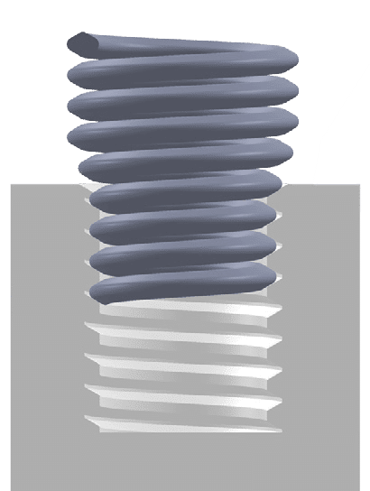
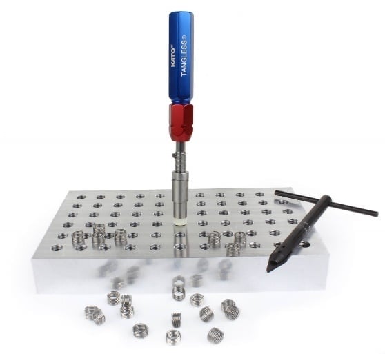
Step 5 – Installation
The installation depth depends on the presence of a countersink. From ¾ to 1-½ turns below the surface if a countersink is present, ¼ to ½ turn below the surface if it isn’t. Tangless inserts can be installed with various manual, electric, or pneumatic tools. The choice of the most effective installation tool depends on various factors. Consult with our technicians, and they will be able to suggest the suitable system based on your application.

When using Tangless inserts (without a tang), there are no additional operations to be performed.
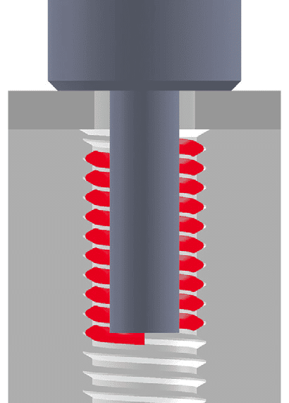
Step 6 – Tang removal
The removal of the tang is always recommended to ensure that the insert is threaded through the maximum number of coils, thus ensuring better retention and greater locking torque when using self-locking inserts. The removal of the tang is also mandatory in all military and aerospace applications and advisable in all critical applications, as under heavy loads, the tang can break and cause damage to equipment. The tang removal can be done with pliers for larger diameters or with a punch slightly smaller than the internal diameter of the threaded insert or with specific automatic spring-loaded tang break-off tools.
.
Removal of the threaded insert
Should any installation error occur, the threaded insert can be removed from its seat using the appropriate removal tools.
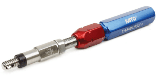
Tangless Inserts: The tool has a similar configuration to the installation one. The difference lies in the extraction hook, which allows the removal of the insert with an unscrewing operation, avoiding damage to the part, thread, and insert. It can also be used to adjust the insertion depth of the insert. The operation is non-destructive and does not cause any damage to the inserts.
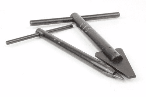
Tanged inserts: The tool appears as a sharp wedge with a T-handle. The blade must be inserted into the first coil of the insert (a hammer may be necessary). After that, it is rotated counterclockwise while continuing to apply pressure until the insert is unscrewed. Extraction is possible only if the insert is not installed too deeply, and the wedge blade can reach the first coil. The extraction operation of tanged inserts often causes damage to the part.
Tangless removal tool
DRILLING –METRIC THREAD

DRILLING – UNC-UNF THREAD
